Proper Gage Selection

PRODUCTION INSPECTION OF THREADED PARTS

The inspection of threaded parts can be approached in two general ways. The individual elements that make up the complex form that is the thread, can each be measured and the results can be compared with a set of standards for these elements. The other method of inspection is to check the thread as a Unit for Interchangeability and function by use of Go and No Go fixed limit gages.

The first method individually measures such variables as lead, uniformity of helix, flank angles, taper, roundness and surface finish, as well as the major diameter, minor diameter and pitch diameter. This method is rarely used in the routine inspection of production parts but is usually limited to the inspection of thread gage themselves, or an analysis of production parts that limit gages have shown to be faulty. This will be discussed in more detail in the section dealing with the measurement of thread gages.

The second method, which is known as the “virtual diameter or effective size gaging practice” provides the ability to check threaded parts accurately and quickly for function and also to provide a definite basis for acceptance or rejection. This is the method in general use by means of Go and No Go thread plug and ring gages.

The Go, or maximum metal limit gage, makes certain that the parts may be assembled by controlling the maximum tightness or minimum looseness of the mating parts. This gage simultaneously checks as many elements of the thread as possible.

The No Go, or minimum metal limit gage, represents the minimum limit of the external thread or the maximum limit of the internal thread.

In order to secure workable knowledge from the gage, it is necessary to know which element is exceeding the specified tolerance. Therefore, a No Go gage checks the No Go limit of one element only.

In the Unified and American National series this is usually the pitch diameter because it is this dimension that controls the quality of fit. Other thread series occasionally use more than one No Go gage, each to check a different dimension. Since the No Go gage is a minimum metal limit gage, all parts should be considered acceptable that either do not enter the gage, or upon entering, develop a definite metal to metal drag before the third turn of engagement.

The gage should not be forced by applying greater torque than is necessary to obtain a drag fit. The purpose of a gage is to control the quality of production. Wear and abrasion from parts being gaged will, in time, alter the size of the gage.

Plug gages get smaller with wear, thus Go gages which were of “W” tolerance when new would soon wear until they were out of the permissible part tolerance limit. Wear on Go gages is much greater than on No Go gages since a Go gage has full engagement in each part checked.

A worn No Go gage tends to restrict parts to the middle of the part tolerance but it will reject parts that are actually still within the product tolerance.

THE GAGE FOR YOUR JOB

Since the cost of gaging is a definite cost of manufacture, certain practicalities must be recognized in regard to maximum metal limit and minimum metal limit gages. In the first place, absolute accuracy cannot be obtained commercially since the gage maker must have some tolerance. The smaller the tolerance, the more expensive the gage to manufacture.

In the second place, absolute size is impossible to maintain since gages wear with use. Recognition of these facts leads to the necessity of making a proper selection of gages if gaging costs are to be kept to a minimum. The selection of the proper gage will be determined by consideration of the number of parts to be gaged; the materials from which these parts are made; the tolerance, design and material of the gages.

TOLERANCE AS A FACTOR IN GAGE SELECTION

Theoretically the actual size of the gage should be the absolute maximum and absolute minimum size of the part tolerance. This would produce maximum acceptance of usable parts but the exclusive use of basic gages would be very expensive because of their short wear life.

It is more practical to check the part as it is machined with working gages of “Y” tolerance or high limit “X” tolerance. Inspection gages of either low limit “X” tolerance or “w” tolerance are used to check the acceptance or non-acceptance of the part. In a “Y” tolerance gage, the actual size of the gage is moved toward the middle of the product limit.

This, together with the gage manufacturer’s tolerance, gives about fifteen percent of the part tolerance as gage wear life. In normal operation some parts would be in this low fifteen percent and therefore rejected by a “Y” tolerance or high limit “X” tolerance gage, even though the parts were within the product tolerance limit.

Absolute limit, or “W” tolerance gages, which have very little wear life since they are on basic size, can be used to re-inspect the parts rejected by these gages.

By this combined use of gages of various tolerances, it is possible to obtain maximum gage wear life and hence low unit gaging costs; while at the same time having the maximum acceptance of usable parts.

No Go gages are not made in “Y” tolerance although in some situations a special plus tolerance No Go gage is used. Since this gage is outside the product part tolerance, marginal parts must be re-inspected with a high limit “X” or “W” tolerance gage in order to eliminate oversize parts.
Pin Gage Measuring

MEASUREMENT OF THREAD WORK PLUG GAGES AND THREAD SETTING PLUGS

The measurement of thread plug gages can best be accomplished by the individual examination of the elements making up the gage. The elements of major diameter, pitch diameter and minor diameter, as well as the thread flank angle and the lead-both linear and helical-all affect the function of the gage; therefore, each element must conform to closely held standards.

Errors or variation in the thread flank angles and the lead also affect the measurement of the pitch diameter. Hence they must be closely held to prevent a false pitch diameter reading.

O.D. AND P.D. MEASUREMENT

The measurement of the major diameter does not present a great problem since it can be measured directly. It usually has liberal limits since its function is to check a cleared diameter in the thread to be measured. The measurement of the pitch diameter, on the other hand, presents certain difficulties which may result in uncertainty as to the true P.O. measurement.

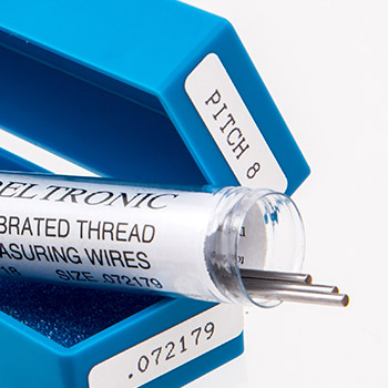
The “three wire” method is the most satisfactory and accurate method when properly used. In this method, small hardened steel cylinders or wires of the correct size are placed in the thread groove-two on one side of the gage and one on the opposite side.

The contact face of the anvil over the two wires must be sufficiently large to touch both wires. The size wire that touches exactly at the midslope of a thread of given pitch is termed the “best size” wire for that pitch.

For 600 threads the best size wire is equal to .57735 x P. In order to measure the P.D. of a thread gage to an accuracy of 0.0001, the wires used must be accurate to 0.00002. In addition to using “best size” wires of known accuracy in measuring P.D., it is also necessary to limit the contact load to avoid deformation of the wires and the gage.

For 600 threads, one pound pressure should be used for pitches finer than twenty and two and a half pounds pressure for threads of twenty pitch or coarser. Measurement of thread plug gages using recommended pressures and wires should be accurate to 0.0001.

There are also some common shop practices which will result in inaccurate P.D. measurements. One is the all too common practice of holding wires down into the thread by means of elastic bands. This prevents the wires from adjusting themselves to the proper position in the thread grooves and will give a false measurement.

Another often used but poor method of measuring is to support the gage on two wires Iaid on a horizontal surface and taking a measurement from this surface to the top of the third wire which is placed in a thread on the top of the gage. If the gage is of large diameter, the weight of the gage will cause distortion of the bottom wires and thus give an inaccurate reading.

Both of these practices should be avoided.

Thread Plug Gages
Pin Gages
View Pin Gages
Pin Gages
My Subtitle
Pin Gage Sets
View Pin Gage Sets
Pin Gage Sets
My Subtitle
Thread Plug Gages
View Thread Plug Gages
Thread Plug Gages
My Subtitle
Thread Ring Gages
View Thread Ring Gages
Thread Ring Gages
My Subtitle
Pipe Thread & Ring Gages
View Pipe Thread Gages
Pipe Thread & Ring Gages
My Subtitle
Thread Measuring Wires
View Thread Measuring Wires
Thread Measuring Wires
My Subtitle
Gage Handles
View Gage Handles
Gage Handles
My Subtitle
Gear Measuring Wires
View Gear Measuring Wires
Gear Measuring Wires
My Subtitle
Hi-Precision Grinding Logo

Grinding & Manufacturing with the Precision of Deltronic

CNC Machining, Grinding, Turning, Drilling, Milling, and Boring